The Challenge

Advancements in the design of rotary and linear motors continue to reduce motor winding inductance. Inductance is fundamental to the magnetic theory of the electric motor, however the act of inducing a magnetic field also produces a voltage drop in the electrical circuit which reduces efficiency. Generally, lower inductance is better from a motor perspective but it creates challenges with sensing, noise and effective motor controller operation.

Many of today’s applications also need high motor speeds operating from low voltage power sources, such as batteries. This combination naturally results in low turn count and its corresponding lower inductance, compounding the control problem by forcing inductance into the single digit micro-Henry range.

With the advent of more efficient magnetic circuit designs realized by better materials and higher strength permanent magnets, the effective number of turns on an electromagnetic phase can be reduced and still produce the same electromotive force (EMF). The electromagnetic phase is made up of coils located spatially around the motor stator or in line within the linear motor forcer. Each phase contains several turns of wire that contribute to the creation of EMF. As the number of turns decreases, the inductance reduced. Low inductance motors can be smaller, lighter, lower cost, and smoother operating, but also introduce some additional complexity when designing the motion control system.

The Solution

The key to achieving the system performance required is in selecting the optimum combination of motor and motor controller.

The Celera Motion motor product portfolio includes a range of slotless rotary motors, air-core linear motors, linear actuators, voice coil motors, and low voltage high speed motors. All of these motor types provide high dynamic response, high efficiency, smooth torque/force creation and compact form factors. They all also have very low inductance, some in the 10-50 micro-Henry range.

There are a wide range of PWM and linear amplifiers available and there are characteristics of the motion control system that will have an impact on the performance of low-inductance motors. This technical note describes two examples to help designers of motion control systems identify motor/controller combinations that will achieve the desired system performance.

Low inductance motors may require 50-100 kHz PWM frequency to minimize current ripple. Typical brushless permanent magnet motor controllers have PWM frequencies in the 20-30 kHz range and some manufacturers offer controllers with PWM frequencies suited for low inductance motors. An alternative is to use linear amplifiers instead of PWM amplifiers but linear amplifiers are typically less efficient, generate more heat and are larger in size than PWM versions.

PWM Induced Current Ripple

Pulse width modulated (PWM) motor controllers are widely used to control brushless permanent magnet motors. In PWM motor controller architecture, voltage is turned on and off at high frequency, producing an average current in the windings. It is desirable for servo systems to be responsive and PWM control allows high voltage to be applied for fast dynamic response while modulating this voltage to effectively control motor phase current.

In an electrical circuit, the equation governing the interaction between voltage, inductance and current is as follows:

V = L * dI/dt

L = Inductance, Henry
V = voltage, Volts
i = Current, Amps
t = Time, Sec

This implies that the current rise with time is related to the voltage/inductance. As inductance decreases the current rises faster and PWM induced current ripple grows. The faster current rise time and larger ripple increases the amount of heat generated and creates additional EMI noise, both of which are undesirable in the designs of complex machinery and equipment.

Example:

24 volts/.00100 Henry = 24,000 amps/sec current rise

At a PWM frequency of 20 kHz with a motor controller applying 5 amps of continuous current, the current ripple could be as high as +/- 0.6 amps. At a PWM frequency of 100 kHz, the current ripple is reduced to 1/5 of the current ripple at 20 kHz.

Figure 2 below shows current ripple induced on a motor by a typical PWM controller.

Low Inductance Motors
Figure 2: With an average phase current of 5 amps, there is ripple above and below this amount related to the voltage, inductance and PWM frequency.

High current ripple is undesirable and will result in higher motor heating and electrical noise in the system. Selecting a PWM motor controller with higher PWM frequency will reduce the amount of current ripple as shown in the example above. Careful attention should be paid matching the motor controller and motor to minimize the current ripple.

Two other alternatives for compensating for a low inductance motor are adding external inductance or using a linear motor controller instead of a PWM controller. However, both of these alternatives compromise efficiency and add cost and size to the system.

Slotless and Air Core Motors

Removing iron teeth from a motor stator or making an air core actuator allows for unique form factors, smooth motion, high efficiency, fast response, and good Kt linearity. Refer to Technical Note TN-2001 for more about slotless technology. Figure 1 below shows an axial view of a Celera Motion AgilityTM Series slotless motor.

With slotless and air core motors, the reduced amount of iron in the motor lowers inductance. Less EMF is created per turn of the phase coil. Small form factors and extremely smooth torque or force is a direct result of removing iron from the circuit. The smooth torque or force means the motor moves with very low velocity ripple, which is a key requirement for many precision motion control applications in imaging, scanning, metrology, photonics, and tracking. The examples below provide some guidelines and considerations to help select the best match of motor and motor controller to realize the benefits of low inductance motor designs.

Rotor with 8 magnets - Figure 4
Figure 1: The rotor is on the inside with permanent magnets attached to a rotor shaft. The stator is on the outside. There is a stator iron ring and potted coils concentric to this ring. The motor contains minimal iron and a large magnetic air gap (which included the magnets and copper). This motor has less than 1 mh inductance. Slotless motors have on the order of 25% of the inductance of traditional motors in the same size.

Example:

Key motor specifications

Ke = 14.8 volts/krpm
Kt = .14 NM/amp
R = 13.6 ohm
L = 0.6 mh
Ir = 1.0 amp (rated continuous current)
24 volts/.000600 Henry = 40,000 amps/sec current rise

At a PWM frequency of 20 kHz, the current ripple could be as high as +/-1.0 amp. At a PWM frequency of 100 kHz, the current ripple is reduced to +/-0.2 amps. A good goal for current ripple is 10% of the rated current for the motor.

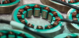
While the torque output versus angle is very sinusoidal and the motion is very smooth with slotless motors, such low inductance will result in a large amount of current ripple relative to the rated continuous current of the motor. This means you have an average of 1 amp with +/- 1 amp of ripple under worse case conditions. At 24 volt bus this motor needs 100 kHz PWM frequency to get close to 10% current ripple.

Low Voltage and High Speed Motors

All permanent magnet brushless motors generate voltage proportional to speed. The maximum speed a given motor will run is directly related to the bus voltage and the voltage constant, Ke. Therefore, low voltage applications will only work with low Ke values. Lowering Ke is done by reducing the phase turn count, which as previously described reduces inductance by the square of the difference.

The following example demonstrates this phenomenon.

Initial Motor Configuration:

Ke = 10 volts/krpm
Kt = .1 NM/amp
R = 1 ohm
L = 1 mh

With a 24 volt supply, maximum speed for this system is 2400 rpm.

New Motor Configuration:

A new project requires a speed of 5000 rpm on 24 volts. Within the same motor frame, the winding can be scaled to lower the voltage constant by adjusting coil turns. The adjusted motor would have the following parameters.

Ke = 4.8 volts/krpm
Kt = .045 NM/amp
R = .23 ohm
L = .23 mh

The maximum speed of this motor is now 5000 rpm. The resistance and inductance scale by a square function due to the properties of the motor phase magnet wire. The volume of motor and the volume of copper are the same. Kt and Ke both scale directly with the number of turns.

Example:

24 volts/.000230 Henry = 104,000 amps/sec current rise.

At a PWM frequency of 20 kHz, the current ripple could be as high as +/- 2.6 amps. At a PWM frequency of 100 kHz, the current ripple is reduced to +/- 0.5 amps. As previously stated, good goal for current ripple is 10% of the rated current for the motor.

Conclusion

As motor design become smaller, smoother and more efficient and responsive, low inductance can creep up as a new challenge for motion control system designers. Inductance can be very low with slotless motor technologies or in low voltage applications that require high speed.

The solution to the problem is to match the PWM frequency of the motor controller to the motor in order to minimize current ripple. Other options include adding serial inductance to the motor phases or using a linear motor controller instead of a PWM controller.

There are many benefits to low inductance, including faster motor response through lower time constants, smoother torque, lower velocity ripple and higher speed when operating from low voltage power sources.