Introduction to EtherCAT operating modes
This paper discusses the modes of operation of an EtherCAT based control system. Selecting the right mode of operation is quite complex, as each mode places different demands on the operating system and processing power of the Master. Application issues such as dynamically changing loads, custom control loop algorithms, and the need for on-the-fly trajectory changes also play a key part in mode selection.
Hierarchy of Tasks
The chart below indicates the task hierarchy in a motion control system. The Operator Interface, Machine Sequencer and Motion Task reside in the Master. The Motor Dependent Servo Loop resides in the Servo Drive. The location (Master or Servo Drive) of the Load Dependent Servo Task is key in the selection of an EtherCAT mode of operation. To a lesser extent, the Path Planner location also plays a role in mode selection. The relative merits of the location of these task are discussed in the next section.
Distributed & Centralized Control
For the sake of simplicity, we will focus on the motion tasks of the machine. The charts below show the allocation of tasks in the three primary configurations. For high-performance systems, Centralized Control and Distributed Control (tightly coupled) are preferred. In both of these implementations, a central path planner generates the trajectories for each Servo Drive. Distributed Control with a local Servo Drive path planner (loosely coupled) is primarily used for stand-alone axes that are not tightly coordinated with other axes. The focus here will be on tightly coupled implementations.
The position and velocity loops are relatively computationally intensive. It is very efficient, particularly for a large number of axes, to distribute these tasks to the Servo Drive thereby reducing the Master computation burden. The position loop sampling period is slower than the current loop (1 msec versus 100 µsec typically) therefore, in Distributed Control the Servo Drive needs updating less frequently further reducing demands on the Master and the speed of the network.
Distributed control satisfies the needs of a wide range of applications. When the gains of the load-dependent servo loops must change dynamically, Centralized Control is preferred. This is often the case for a robotic arm, which experiences a changing load as the arm is extended. The need for changing gains can be handled in Distributed Control by position-dependent gain scheduling lookup tables, but
Centralized Control is a more flexible solution. Another advantage of Centralized Control is the flexibility to implement custom control algorithms in the Master.
As discussed, in Centralized Control, the Master must update the Servo Drive current loop at a very fast rate. A major consequence is that a Real-Time Operating System (RTOS) is almost certainly required, increasing cost and complexity. Another important consideration is network latency. The Master must read position via the network before generating a current command update. The subsequent network lag may compromise servo performance.
A legacy hybrid architecture, not typically implemented today, places the position loop in the Master and the velocity and current loops in the Servo Drive. This solution dates back to when servo drives were controlled by an analog velocity command from a motion controller. The architecture has been supplanted by distributed and centralized control.
Servo Drive Buffering & Interpolation
Buffering and interpolation in the Servo Drive are two techniques for reducing the real-time burden of the Master. For example, trajectory position points can be pre-calculated and stored in each drive. A sufficient number of points can be buffered to accommodate latency in the operating system. A drawback of this technique is that if the trajectory must be changed dynamically, the buffer must be emptied and refilled with the new path. A typical example of this would be cobot obstacle avoidance.
Many Servo Drives have linear or polynomial (cubic/quantic spline) interpolators. This is particularly useful for servos with fast loop update rates. For example, a high-performance drive might have a position loop sampling time of 40 µsecs. For a multi-axis configuration, updating the commanded position at this rate would place a heavy burden on the Master. It is more efficient for the Master to feed position points to the Servo Drive interpolator every msec. The interpolator in turn updates the position command to the servo loop at the sampling rate.
Synchronizing Servo Drives
The primary operating modes of EtherCAT involve the transmission of periodic data with a predefined cycle time. There are two ways to synchronize the Servo Drives to this cycle. Both make use of the EtherCAT Servo Drive Controller (ESC) hardware resident in the drive.
Sync Manager Event Mode
The ESC generates an interrupt to the drive processor when master data is received. The local cycle of the Servo Drive is triggered by the interrupt event.
SYNC0 Synchronization Mode
The Servo Drive samples the data after the ESC SYNC0 pulse, which is configured to occur at a predefined number of local clock cycles. Note that all clocks on the network are synchronized at startup.
The Master typically runs on a complex PC operating system, which may not have the real-time performance of the Servo Drives. There can be timing jitter on the data that the Master sends. SYNC0 synchronization mode can resolve the problem. In this mode the Master can compensate for its worst-case jitter by transmitting data to the Servo Drives sufficiently early, so that the data will be received before the SYNC0 signal. The Servo Drives will not use the process data received until the SYNC0 occurs, therefore the system can remain synchronized even with timing jitter in the Master.
CANopen over EtherCAT (CoE)
CANopen is a communication protocol for embedded systems used in automation. It is managed by CAN in Automation (CiA). CANopen defines specific profiles for different types of devices: servo drives, I/O modules, etc. CoE enables the complete CANopen profile family to be utilized on the much higher speed EtherCAT network. CiA DS402 is the device profile for servo drives and defines the available operating modes. The most widely used modes are outlined in this paper.
Real-Time Communication and Configuration
DS402 also defines two methods of communication. Both methods communicate via the object dictionary in the Servo Drive. The object dictionary is simply a block of memory that can be accessed by both the Servo Drive and the Master. Object examples are Actual Current (status), Target Position (command), Current Loop Proportional Gain (parameter).
Service Data Objects (SDOs)
SDOs are used for drive configuration after power-on, for PDO mapping (see next section) and for infrequent low priority communication. An SDO addresses a specific parameter in the object dictionary for writing or reading. SDO communication involves handshaking (request/acknowledge) between the master and servo drive.
Process Data Objects (PDOs)
PDOs are for real-time communication. There is no handshaking for maximum real-time efficiency. A PDO does not directly address parameters in the object dictionary, further improving efficiency. Instead, a PDO carries an identifier and data. The data for a specific identifier is mapped (via SDO) to specific parameters in the object dictionary during the network initialization phase. The basic idea is that both the transmitter and the receiver know ahead of time, how the PDO content is to be interpreted.
The data content of a PDO is flexible and configurable. In reality, drive manufacturers often dedicate specific PDOs to specific operating modes. If configurable PDOs are provided, the parameters which can be included in PDO data are limited to a subset of objects in the dictionary. Servo gains are generally not included in the subset so real-time gain setting may not be possible.
PDOs are used by all EtherCAT operating modes.
CST – Cyclic Synchronous Torque Mode
CST is the primary mode for centralized control. The Master closes the load-dependent servo loops and sends a current (torque) command to the Servo Drive. Drives with very fast current loop update rates may use interpolation, as shown in Figure 1, to reduce the burden on the Master and the network. The commanded current is the Quadrature (Q) torque producing component of the current vector. The drive servos the Direct (D) component to zero for optimal magnetic field alignment. Some drives have the option to accept both D and Q current commands if field weakening for higher speed is employed.
PROS: maximum flexibility for real-time adjustment of load-dependent servo loop gains, ability to implement custom load-dependent servo loop algorithms
CONS: typically require Master RTOS, increased Master computational burden, fast drive update rate, potential reduction in servo performance
Cyclic Synchronous Position Mode (CSP)
CSP is the primary mode for distributed control. The Master path planner generates trajectory points at a periodic rate equal to (or an integer multiple of) the Servo Drive position loop sampling time. All servo loops are closed in the Servo Drive. There is no network lag between loops so optimal tuning is possible. Some drives with very fast sampling times allow buffering of points, as well as interpolation between points transmitted at a slower rate than the sampling time.
PROS: highest servo performance, flexibility to buffer and interpolate to reduce Master and communication burden
CONS: less optimal for applications requiring real-time adjustment of load-dependent servo loop gains, custom loop architectures typically not possible
Position, Velocity, Time Mode (PVT)
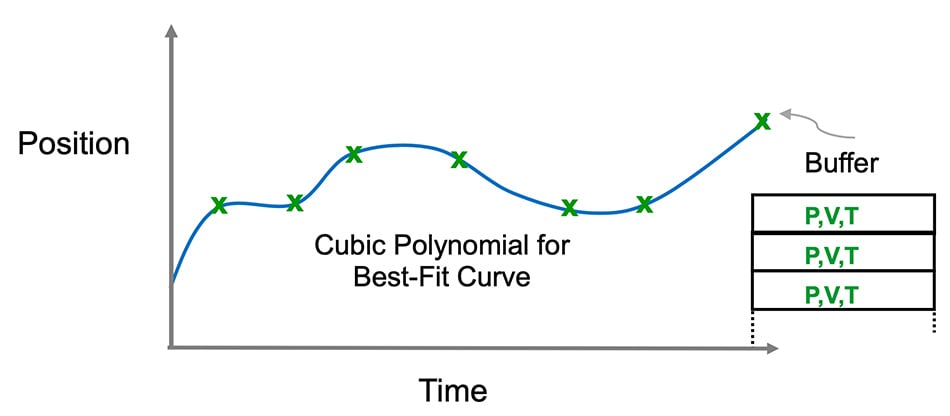
PVT, a non-cyclic distributed control mode, is often used in CANopen based applications as it places minimal burden on network speed. PVT Mode is less employed in the much faster EtherCAT system, CSP
Mode being preferred for its potentially tighter synchronization. In PVT mode, the Master generates Position, Velocity, Time vectors, which are buffered in the Servo Drive. The Servo Drive performs polynomial interpolation to generate a best-fit curve. Note that just a few PVT vectors are required – particularly for straight-line segments.
PROS: places minimal demand on network and real-time capability of Master operating system
CONS: requires buffering so it is less responsive to real-time path changes, curve fitting may result in less precise multi-axis path following
Profile Position Mode (PP)
PP Mode makes use of the internal profile generator of the Servo Drive. The Servo Drive can be configured for trapezoidal or S-curve profiles. The Master specifies the move distance, speed, acceleration, deceleration and jerk. Compound move profiles can be generated by updating the target position before the move is completed. PP Mode is primarily used for stand-alone axes which are not part of a coordinated set.
PROS: places very low demand on network and real-time capability of Master operating system
CONS: not a solution for tightly coordinate multi-axis motion
Cyclic Synchronous Velocity Mode (CSV)
CSV Mode is primarily used for speed control in applications like AGVs, spindles, and electronically geared web lines. The Master generates a command for the Servo Drive velocity loop. Servo Drives with high-speed loop update rates often have interpolation capability as shown in Figure 5 below. CSV Mode can be used in a hybrid architecture with the position loop in the Master, and the velocity and current loops in the drive. The hybrid architecture is used for the pros and cons below, as CSV for speed control does not relevantly compare to the position control modes discussed.
PROS: distributes some of the computational burden of the Master to the Servo Drive, reduces network burden
CONS: not ideal for dynamically changing loads requiring real-time velocity loop gain changes
Conclusion
For most tightly coordinated motion control positioning systems, CSP Mode is the preferred solution.
Most servo drives have the flexibility to provide buffering and interpolation to reduce the burden on the Master OS and the required update rate. For applications requiring custom servo algorithms or real-time changes to load dependent servo loops, CST is recommended. CSV Mode is primarily used for speed control applications.


