Overview
This paper discusses how to specify the shunt resistor used when a servo drive is in regenerative braking mode. The concepts of regenerative braking and capacitor energy storage are explained. Fusing and the wiring of both single and multi-axis systems are reviewed. The paper concludes with a worked example.
Shunt Breaking Resistor Basics
Motor Power Flow
During normal operation, the servo drive receives electrical power from a DC bus supply and outputs a controlled electrical power through the phases of the motor. Then the motor converts this electrical power to mechanical power that moves the load:
Figure 1
In regenerative mode the motor acts as a generator whose load is the servo drive and the DC bus supply. In the same way the DC bus voltage is stepped-down in normal operation, the generated voltage is stepped-up in regenerative mode, which causes the DC bus voltage to increase as its capacitance is charged by the incoming current. If the bus voltage increases too much, the power transistor rating can be exceeded causing component failure. A shunt braking resistor can be connected to the servo drive to dissipate this excess of regenerated energy, preventing potentially damaging voltage levels.
During regenerative braking, the power stage of the servo drives operates in reverse, boosting (or stepping-up) the DC bus voltage. This means the DC bus voltage (and supply) can be higher than the value of BACK-EMF of the motor at the given speed.

Figure 2
In some cases, the shunt braking resistor may be avoided or minimized in the case of:
- Battery powered systems that allow recharging and have no reverse blocking diodes.
- Systems with large DC bus capacitance that can store enough braking energy.
- Systems that use electromagnetic brakes that dissipate the energy mechanically.
Shunt Wiring
Shunt Wiring of a Single Drive
The typical wiring circuit of a shunt resistor connected to a single servo drive is shown next. The shunt is connected between the power supply positive and the SHUNT_OUT of the drive; this is an open drain high current output.
An additional fuse or resettable over-current protection could be added to protect the resistor against fire or explosion in case of an unpredictable overload or a wrong configuration of the shunt activation voltage that sets the SHUNT_OUT active at all times.
Note that the fuse blowing may cause a cascade effect destroying the drive and the power supply by an over-voltage situation, which may be worse than overloading the resistor. Therefore, the fuse should be designed to never blow on nominal conditions, only as a last resort to prevent fire or dangerous temperatures on the braking resistors. The fuse is not necessary when:
- Using a resistor whose nominal power at working temperature exceeds:
Presistor > Vmax(supply)² / R
In terms of safety, this is the best approach that guarantees that the shunt braking resistor will always work reliably. However, it typically leads to over-sized resistors.
- Using safety resistors that are designed to fail in open-circuit fashion.

Figure 3
Shunt Wiring of Multiple Drives Sharing a Power Supply
When wiring multiple drives in parallel to the same power supply or battery, a single shunt resistor could be shared among all the axes. Do this only if the braking current of all the axes does not exceed each individual servo drive’s shunt current capacity.
Paralleling the shunt output is possible as the drives have an open drain output.

Figure 4
Using PWM modulation for driving the shunt braking resistor
Modulating PWM might be equivalent to “changing the effective value of resistor”, but it:
- Increases EMI
- Increases power losses
While PWM modulation is quite handy during design stage, it should be avoided on the production stage by using a well-chosen shunt braking resistor.
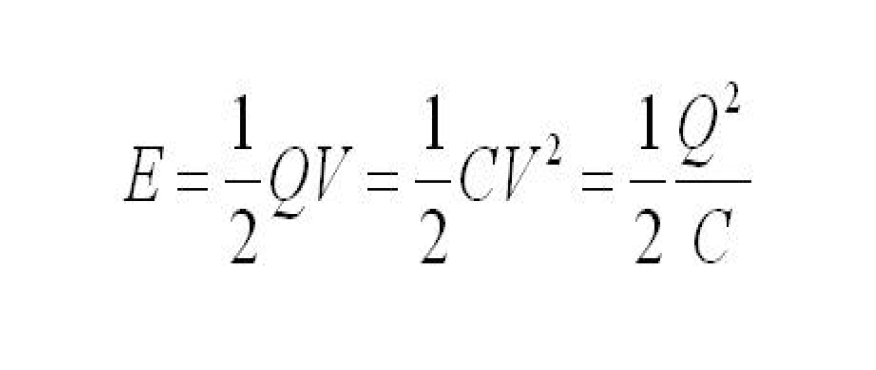
Energy that can be stored on the DC bus capacitor
Using a DC bus capacitor can be sometimes a cheap alternative to using a shunt braking resistor to avoid an uncontrolled increase of the DC bus voltage in case of re-injection. However, this method has serious disadvantages:
- Large voltage swing from nominal to max is needed to be effective. Watch for the power supply overvoltage disconnection threshold.
- Huge capacitors are needed.
- Capacitors are typically dimensioned for EMI rather than energy storage in low voltage DC drives.
Quick guide for shunt braking resistor choice
The simplest approach to resistor sizing is to use the online calculator for sizing a shunt resistor for regenerative braking.
If a manual process is preferred, the following steps provide a safe, conservative approach to size the shunt resistor for most systems (we will consider that 100% of deceleration energy goes to the shunt resistor). In case of doubt, it is better to include the shunt braking option and, if finally not needed, remove it.
1) Determine your system max kinetic energy (Ek) at max speed and/or max potential energy (Ep) at max height. Calculate the mechanical energy Em:
Em = Ek + Ep
Include motor, gearing and load inertia. For vertical loads, potential energy may be the biggest contribution.
2) Determine the min deceleration time (tdec) and max number of decelerations per second (Db).
3) Determine the resistor Ω value with the following formula: R ≈ Vmax(supply) * 1.1 / i(shunt) where:
Vsupply(max) (V): power supply max voltage including tolerances
i(shunt) (A): deceleration current (if unknown, use the drive peak current)
4) Choose a standard resistor with value close to R.
5) Determine resistor average power Pav by:
Pav = Em * Db
Consider power-temperature derating on the resistor datasheet.
In case the duty cycle of the application is unknown, consider the highest number of deceleration cycles per second that can be physically made.
An alternative approach is to design the shunt to operate 100% of the time. In this case, the power of the resistor must be Pav = Vmax(supply)² / R. This approach is conservative and may result in very big resistors, but is the safest approach.
6) Determine the resistor peak (overload) power Ppk by the maximum of the following equations
Ppk = Maximum( Em / tdec ; Vmax(supply)2 / R)
Ensure the integrity of the chosen resistor. The peak power depends on peak time. Check the resistor datasheet. The Ppk (5 s) is typically: Ppk(typ.) = Pav * 5 for wire-wound resistors.
7) Connect the shunt resistor according to the installation manual. Provide generous dissipation to the resistor if Pav is close to the resistor nominal power.
8) Configure the servo drive shunt activation voltage. Ensure the configuration is well stored in the nonvolatile memory. Ensure the shunt activation voltage is always > nominal supply voltage.