


")

Non-contact, inductive angle encoders for high-precision, reliable measurement in harsh environments.
- Non-contact technology for high reliability in extreme environments
- Proven in medical, industrial, aerospace, & field robotics applications
- Over 500 million product configuration options available
Scroll to IncOder overview

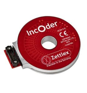
IncOder® Series – Robust and precise inductive angle encoders
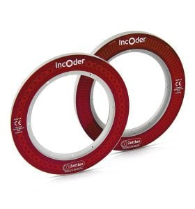
Ultra IncOder™ Series – Pre-calibrated IncOder for increased accuracy

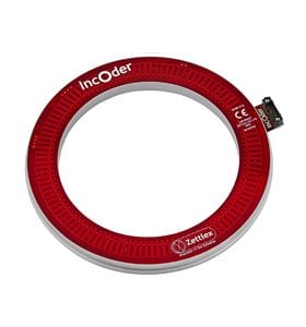
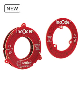
IncOder® CORE – Compact, Lightweight, Inductive Ring Encoders
Robust Angular Position Measurement for Extreme Environments
Zettlex IncOders are non-contact devices for precision angle measurement. They work like a transformer, using an inductive technique. IncOders may be considered as an inductive angle encoder.
IncOders are ideally suited to harsh environments – where potentiometers, optical or capacitive devices may prove unreliable.

High-reliability Inductive Angle Encoder Technology
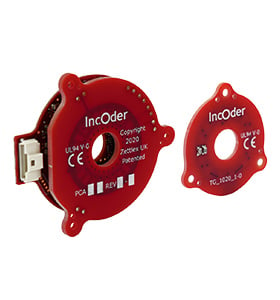
IncOders have 2 main parts – a Stator and a Rotor – each shaped like a flat ring. The large bore makes it easy to accommodate through-shafts, slip-rings, optical-fibres, pipes or cables.
The Stator is powered and the Rotor is passive. The Stator contains the electronics to receive power and generate an output signal. The output signal from the Stator shows the true absolute angular position of the Rotor relative to the Stator without the need of any motion.
Simple Installation; ‘Fit and Forget’ Technology
IncOder inductive angle encoders do not require compliant or special couplings and the Rotor & Stator can simply be screwed to the host product. Precise mechanical mounting is not required and there are no bearings.
Whereas optical or capacitive angle encoders can be unreliable in harsh conditions – notably with condensation or dust – Zettlex angle encoders are generally unaffected by foreign matter and IP67 rated versions are available. Unlike capacitive devices, there is no need to earth the Rotor or Stator. Robust, hard-anodized aluminium alloy housings and monolithic constructions are used throughout.
There are no contacting, delicate or wearing parts, so there is no need for periodic replacement, service or maintenance. In other words, IncOder angle encoders are true ‘fit and forget’ devices.

Inductive Angle Encoder Specifications / Options
Mechanical Formats
12 mechanical formats featuring screw or servo clamp Stators with screw format, set screw, shaft clamp and plain Rotors, duplex Stators and Rotors.
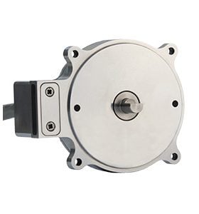
Packaged formats include servo clamp or screw flange.
IncOder Size Options (Stated as Outer Diameter)
37, 58, 75, 90, 100, 125, 150, 175, 200, 225, 250 & 300mm
Resolution Options
9 to 22bits & user selectable pulses per rev for A/B pulse outputs
Connection Options
Axial connector, radial flexi (with or without connector) & integral axial cable
Voltage Options
5, 12 or 24VDC
Communication Interface Options
SSI, ASI, SPI & BiSS-C
Analogue voltage
A/B/Z pulses
Extended Range Options
(Not Typically Required for Most Application Types)
Ultra high shock & vibration
Cold temperature option to -60° Celsius
High temperature option to +105° Celsius
Surtec650 surface finishes
Prolonged immersion, salt spray or extreme dust conditions
High Pressure
Product Documentation
- Ultra IncOder Series – Brochure
- IncOder Series – Brochure
- IncOder CORE – Brochure
- Mini Ultra IncOder Range – Product Guide
- Midi Ultra IncOder Range – Product Guide
- Mini IncOder Range – Product Guide
- Midi IncOder Range – Product Guide
- IncOder CORE – Product Guide
- 58mm Shaft IncOder Range – Product Guide
- IncOder & Controller Compatibility Table
- IncOder Range ROHS Certificate
- IncOder REACH Statement
Field Calibration IncOder
CAD Files
We have a comprehensive library of 3D CAD files available to assist designers in the integration of our inductive angle encoders. Click the button below to view available files, or contact us if you’re looking for something specific that is not listed.
FAQs
Have a question about the IncOder product range? Here we answer a selection of frequently asked questions.
If your question doesn’t appear, please get in touch with one of our experts.
The IncOder CORE feedback sensor should be considered where the need for an inductive encoder solution with significantly reduced weight is important, particularly in low inertia, low energy applications e.g. camera gimbals, robotic joints, and rotary actuators.
Additionally, IncOder CORE is more economically priced compared with IncOder, for medical and industrial OEM solutions focussed on scalability.
IncOder CORE is suited for motion systems do not necessarily require the extreme environmental performance of IncOder however want to take advantage of its high reliability and robustness, immunity to dust and dirt, high resolution measurement output and easy-to-install capabilities.
IncOder CORE can be purchased by specifying your sensor part number with CORE-X-XXX… on your Purchase Order.
IncOder CORE can be purchased through our online configurator here.
SSI, BiSS-C, SPI and ASI (Asynchronous Serial Outputs). A complete list of protocol options can be found in the datasheet.
Ultra IncOder Series features the same form, fit, and function device as the original rugged IncOder Series, but with at least a 50% improvement in accuracy. Taking advantage of high measurement repeatability, each Ultra IncOder is pre-calibrated against a highly accurate measurement reference in production, diminishing inherent sources of non-linearity. More tightly controlled tolerances, in-housing metalwork, and surface finish are employed in the design, enabling users to install the encoder to tighter mounting tolerances required. An accuracy certificate is included with each unit.
Ultra IncOders are available in Mini (37 to 58 mm OD) and Midi (75 to 300 mm OD) sizes.
Click for further details of our Ultra IncOders.
By default, IncOder only outputs Single Turn position data, being angle position data over 1 rotation (360 degrees). Multiturn encoders have the ability to count Multiturn data (the number of complete rotations of the sensor). Multiturn IncOder options are available for our Midi IncOder series by specifying the following protocol production options: SSI31, SSI32, SPI31, ASI31, ASI32 or BIS32. SSI based options provide 8 bits of turn count (0-255). BiSS, SPI and ASI options provide 12 bits of turn count (0-4095).
Conventional multiturn devices are able to increment Turn Count data when the device isn’t powered, which is not the case for Multiturn IncOder where Turn Count data doesn’t change when the device isn’t powered.
When power to Multiturn IncOder devices is removed, this event will be detected and position information is stored in non-volatile memory. Once the device is powered again, this data is recovered.
Note that if the Midi IncOder moves >1.5 degrees, an error condition will persist. The Midi IncOder will continue to indicate this error until the error is reset. Further details of this process can be found in our product guides.
Configure a Midi IncOder
Configure a Midi Ultra IncOder
Read more about Multiturn IncOder here.
Multiturn IncOders can be selected by choosing one of the protocols: SSI31, SSI32, BIS31, SPI31 ASI31 or ASI32.
Multiturn IncOder provides single turn resolutions of:
- up to 21 bits for sizes 150 – 300mm OD,
- up to 20 bits for sizes 75 – 125mm OD.
Multiturn IncOder provides multiturn resolutions of:
- 12 bits (0 – 4095 counts) for BIS31, SPI31, ASI31 and ASI32,
- 8 bits (0 – 255 counts) for SSI options.
No. If the IncOder were to move whilst the power is off, then when power is re-applied the IncOder cannot determine how many revolutions may have been performed. It is a requirement that the IncOder does not move by more than ±1.5 degrees whilst power is off. Multiturn IncOder is an absolute inductive encoder with non-volatile turn count storage. Turn count is stored in this non-volatile memory so that it is retained during “loss of power” events. When power is re-established, the turn count is retrieved and turn counting will continue.
See our Multiturn IncOder page for more information.
The maximum speed for any IncOder type is specified in the Product guide and is dependent on the size of the IncOder, as well as the communication protocol type. It is the maximum speed at which position measurement will be taken. The fastest physical speed is specified as 10,000 rpm. In some cases, such as for Mini IncOders and Mini Ultra IncOders it may be possible to measure position at a faster angular speed than specified. Please contact Celera Motion for more information.
The term IncOder comes from a combination of inductive and encoder. Most angle encoders use optical or capacitive techniques and these can be unreliable in harsh environments where foreign matter, such as dirt or condensation, can interfere with encoder operation. Traditional inductive position sensors, such as resolvers or LVDTs, use transformer constructions and they operate well in harsh conditions but they are too bulky and expensive for many applications. IncOder offers the best of both worlds – reliable inductive technology but the ease, compactness and convenience of an encoder.
Yes – the Zero Point can be changed using the Zero Set and Zero Reset lines on the electrical interface. The Zero Set signal will set the current IncOder position as the Zero Point (held in memory when power is removed). Zero-Reset signal will reset the Zero Point to the factory setting (held in memory when power is removed).
To use, the relevant connection should be connected to an electrical ground (<0.5 V) for at least 3 seconds at power-up but left unconnected (i.e. open circuit) during operation.
IncOder CORE features the same robust sensing technology, electronic design and software components as IncOder, but in a significantly lighter package. By designing the stator and rotor PCB structures to the appropriate thicknesses, and integrating mounting features into the board itself, the sensor board becomes self-supporting enabling a significant decrease in sensor weight compared to the housed IncOder variant. The cost of the sensor is also appreciably smaller than IncOder. IncOder offers a gear change in environmental robustness due to its housed and potted design: broader operating temperatures, high shock and vibration performance, shielding, operation in wet environments.
IncOders work in a similar way to brushless resolvers and rotary variable transformers. The IncOder Stator receives a DC power source and produces a low power AC electromagnetic field between the Stator & Rotor. This field is modified as the Rotor rotates. The field is sensed by the Stator and the rotation angle output as an analogue or digital signal. Unlike resolvers, IncOders use laminar circuits rather than wound wire spools. The patented technology enables IncOder’s compact form, low mass, low inertia and high accuracy without high precision installation.
Please see our “How Inductive Sensors Work” article here:
Yes. Measurements will be the same before and after power interruption. No motion is needed at start up.
For further reading – What is an absolute encoder?
Yes. If BIT shows an internal error then an error signal is generated. The BITs include continuity/damage, presence of Rotor, in-range Rotor, gross electromagnetic malfunction, window watchdog timer, power on reset, power brownout reset, timeouts for clock input, read/write and internal flash data memory value checks.


