Precise, reliable non-contact inductive rotary position sensors for Original Equipment Manufacturers.
- Non-contact technology for high reliability in extreme environments
- Proven in medical, satcom, industrial and field robotics applications
- Suitable for high and low volume production requirements

Robust Rotary Sensors for Extreme Environments
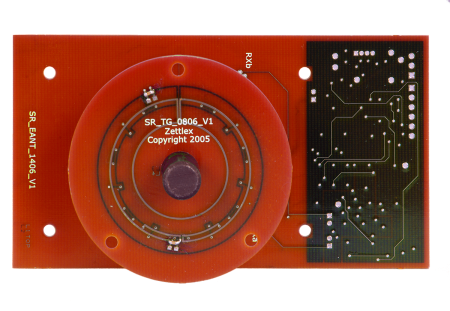
Zettlex rotary position sensors are non-contacting, absolute position measuring devices. They utilize a unique inductive position sensing technology and comprise two main components – a Target and an Antenna. The Antenna is powered and the Target is passive. An electrical output from the Antenna shows the rotary position of the Target relative to the Antenna.


Rotary Position Sensors for OEM Applications
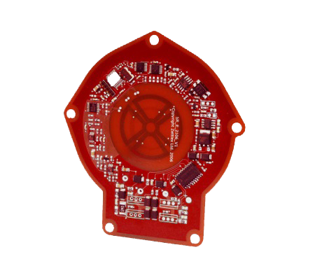
The rotary sensors are supplied in unpackaged form, making them ideally suited for inclusion within a customer’s host product such as a PTZ camera, robotic arm or gimbal system. The Targets and Antennas can simply be secured to the product with screws or adhesive – precise mechanical mounting is not required.
Zettlex rotary sensors are ideally suited to harsh environments where electrical contacts or optical rotary sensors would prove unreliable. Operation is unaffected by condensation or dust.
IncOder CORE – Frameless Inductive Encoders
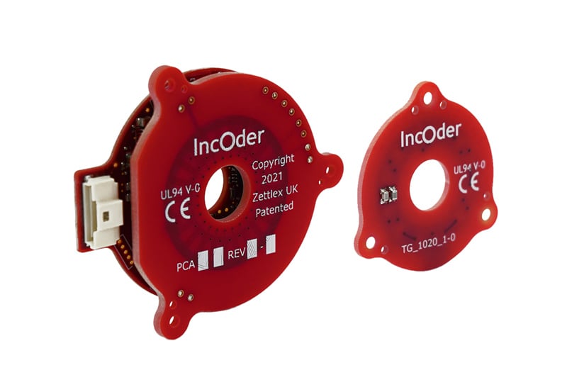
IncOder CORE is an off-the-shelf, lightweight absolute angle encoder series, fully contained in a frameless printed circuit board kit. The ergonomic hollow bore design is suited for integration into rotary actuators and robotic joints, available with a range of configuration and customization options. The 44mm IncOder CORE can be configured to output up to 17-bits of absolute position data in a range of protocol options including SPI, BiSS-C, and SSI.
IncOder CORE enables a shortened pathway to design an OEM rotary sensor with rapid derivative customization possible. This includes changes to installation mechanics, as well as larger sizes and shorter axial height options. Please contact our sales team for more information.


Rotary Position Sensor – 16384 Counts Per Rev
Angular measurement sensor – 14 bit (16384 cpr) – easy installation, digital data output. Unpackaged for OEM use.
- Absolute position measurement
- 360 degrees rotary measurement
- 14 bit resolution = 16384 cpr = 0,022 degrees
- ± 1 LSB repeatability
- -45 to +85ºC operating temperature
- Low profile rotary sensor

Rotary Position Sensor for OEM Applications
A pair of 14 bit, hollow shaft, absolute encoders with a single power supply and single digital data stream output. Ideal for robotic arms, P&P units, gimbals, PTZ units etc.
- 14 bit resolution
- ±1 LSB repeatability
- Insensitive to dust, condensation, foreign objects
- Simple installation

OEM Programmable Rotary Sensor
Unpackaged rotary sensor with analog and digital outputs with PC programmable functionality.
- 4…20mA + up to 3 digital (switch style) outputs
- Rich PC programming functionality including switch points, cal. curves, manufacturer data etc.
- Can be encapsulated for harsh environment operation
- Lightweight, low inertia moving parts
- Needs no precision assembly
- Impermeable membrane can be situated between electronics and moving target
- 8-28VDC supply

IncOder CORE – Frameless Inductive Encoder Series
- Absolute Position Measurement
- Compact, Lightweight all-PCB construction
- High resolution digital output
- BiSS-C, SSI, SPI, Asynchronous serial protocol options
- Customization and additional size options possible
OEM Rotary Position Sensors Documentation
FAQs
Have a question about our OEM rotary sensors? Here we answer a selection of frequently asked questions.
If your question doesn’t appear, please get in touch with one of our experts.
The term for one of our products would be ‘absolute displacement transducer’, but for simplicity, we use the term position sensor. Other applicable terms might include position encoder, position transmitter, rotary encoder, linear encoder, rotary sensor, shaft encoder, angle resolver, angle synchro, displacement transmitter.
You can find further information in our technical paper ‘Position Sensors – Choosing the right sensor’.
As a custom solution, the maximum number of sensors per set of electronics is determined by the maximum permissible response time per sensor. If we consider the example of a Zettlex sensor taking 1 millisecond per measurement and a maximum response time of 250 milliseconds, then with a simple multiplexing scheme, the maximum number of sensors is 250.
This number can be increased with a more sophisticated multiplexing algorithm, for example, sampling the less frequently used or less important sensors less frequently.
A custom Zettlex Electronics Module can also handle inputs from other elements such as switches.
Yes, it is possible to mount the rotor to a metal housing with a plastic buffer. The buffer would need to be at least 3 mm thick to ensure the metal is sufficiently far away from the rotor so as to not adversely impact the sensor performance. An example would be to use a machined plastic shim or 3mm nylon spacers. Please contact our Applications Engineering team for more guidance.
Zettlex inductive encoders are generally not susceptible to emissions from other sources due to a number of factors: – the Receive circuits are arranged as balanced quadrupoles (thus negating the effect of incoming plane waves), the signal from the Target is at a highly specific frequency and the sensor uses synchronous detection.
Zettlex sensors are suitable for medical and SATCOM applications where permissible emission susceptibility is particularly stringent.
The IncOder product range is particularly robust in harsh EMC conditions because it is housed in a metal casing that acts as a Faraday cage.
For all Zettlex inductive encoder products, the air gap (axial separation of the target and antenna) is specified in the product datasheet. Generally, it is easiest to answer this question using a couple of examples:
In a rotary example, with an Antenna O.D. of 50 mm and an I.D. of 20 mm, then the equivalent Antenna width is 15 mm (the thickness of the annulus). The maximum working distance of the Target from the Antenna will be about half the effective Antenna width, 7.5 mm. We would normally recommend a stand-off distance of <1/4 Antenna width, about 3-4 mm.
Learn more about rotary inductive encoders here.
If we consider a linear Antenna 10 mm wide and 100 mm long in the measurement axis, then the maximum working distance of the Target from the Antenna will be about half the Antenna width, 5 mm. We normally recommend a stand-off distance of <1/4 Antenna width, about 2-3 mm.
Learn more about linear inductive encoders.
We have designed and manufactured many linear sensors with a maximum full-scale deflection of 5 mm and a resolution of <1 micron.
For rotary devices, we have built sensors with targets and diameters of 12.7 mm.
A number of parameters related to ‘accuracy’ are important for sensors. These are usually linearity, resolution, and repeatability. The exact parameters for any series of Zettlex sensors primarily depend on the sensor geometry and, in particular, any variability of the position of the target in axes other than the measurement axis. Other factors affect performance to a much lesser degree.
As a general rule:
- Linearity is typically <<1% of full scale and can be <0.0001% of full scale
- Resolution is typically <24 bits but most commonly 10, 12, 14, 16 or 18 bit
- Repeatability is typically +/- 1 least significant bit of the quoted resolution
For our rotary IncOder sensor, we are able to improve linearity by up to 50% by pre-calibrating each stator-rotor pair. Please see our Ultra IncOder Series for more details.
Please complete our Contact form and we’d be happy to discuss how we can help meet your specification needs.
The first stage in developing an application-specific Zettlex sensor is to discuss the specific technical requirements with us. The most important aspects are sensor geometry, accuracy, speed & electronic output. From this a Requirements Specification can be drafted as a first step in the development process – we can help you do this. Celera Motion follows a tried and tested Zettlex custom sensor development process leading to full-scale production.
We look forward to speaking to you!
Yes. It may be possible to integrate machinery control software into the microprocessor containing the Zettlex sensor software.
Power supply, frequency generation, etc. can also be shared between host and sensor system.
Generally, Zettlex position sensors are not susceptible to far field emissions up to field strengths of 150 V/m. This covers the vast majority of possible applications including most medical and aerospace applications. However, in some applications, higher field strengths can be accommodated with the use of special targets or simple, low-cost shielding and earth planes. Zettlex applications comply with EN 68000 and CISPR 25 level 1 or 2.
Yes. As a custom solution, Zettlex sensor software can be parameterized to control multiple sensors of differing geometries.
Generally, a metal exclusion zone is required in the gap between the sensor Target and Antenna.
In principle, a metal shield may be inserted between these components however the skin depth through which the excitation signals can permeate limits the thickness of the metal shield. The lower the excitation frequency, the greater the thickness of permissible metal. The maximum thickness of metal depends on the actual metal. If a metal shield is to be used then non-magnetic stainless steel is most preferred with aluminum, steel, copper, or brass least preferred. Practically, metal thicknesses of <1.6mm would be necessary.
Please note that resolution and accuracy would be limited in such an arrangement.
The cost depends on a number of factors such as measurement specification, size, environmental conditions, and testing requirements. Please contact us with details of your application and we will provide a budgetary quote in a few days. Alternatively, you can find low-volume product costs from our Online Shop.
Link to our Online Shop.
By their fundamental nature, Zettlex sensors do produce electromagnetic emissions. However, these emissions are small and in practice, such emissions are invisible in the Far Field due to the rapid fall off of the field at an inverse cubed rule.
Given the low emissions levels, Zettlex sensors are suitable for sensors in specialist vehicle, medical, SATCOM applications where permissible emission levels are particularly stringent.
Practically, the materials, from which the sensor’s main components are produced, limit the operating and storage temperatures.
Importantly, the sensor’s fundamental operating principles are not affected by temperature. That means Zettlex sensors can operate in relatively low or high temperatures.
Most frequently, the effective temperature range is limited by the electronic components at –40 to +85 or +105 Celsius (i.e. industrial or automotive ranges).
However, it should be noted that the sensor’s electronics can be displaced away from the Antenna. This enables the sensors to be designed such that only the Antenna and Target are placed in harsh temperature environments whilst the Electronics are placed in a more benign environment away from, or insulated from, the harsh conditions.
Ceramic substrates for the Antennae and Target substrates can be used to increase temperature limits.
We recommend exploring our “Accurate Position Measurement in Varying Temperatures” Technical Paper.


