Introduction

Temperature is one of the many limiting factors in the motor selection process that can be easily overlooked, but detrimental to the anticipated motor performance. The allowable temperature rise directly affects the power output of the motor. If temperature is not accounted for, the torque and speed of the selected motor may be insufficient.

This paper discusses the importance of the motor constant (𝐾𝑚) in the motor selection process for thermally limited applications. When temperature and motor constant are overlooked, it is possible that the required power output of a selected motor will not meet the system requirements. This paper will walk you through a few examples of selecting a motor with and without the motor constant.

Thermal Restrictions of a System

Major Heat Sources

Significant heat sources in a system include the motor, drive, and brake.

Motor: as current flows through the copper windings, electrons collide with atoms in the wire. During the collisions, some kinetic energy is converted to thermal energy. This process is known as Joule heating and can be reflected in a simple power calculation. This calculation shows that the higher the current flowing through the winding, the more power will be dissipated.  Additionally, as the copper fill increases in the motor, the phase-to-phase resistance and heat dissipation increase. By minimizing phase-to-phase resistance, Celera Motion’s motors are designed to reduce copper power losses.

Motor thermal heat restrictionsDrive: When the drive delivers current to the motor the power stage heats up due to conduction and switching losses. Celera Motion’s Ingenia Summit Series servo drives are specifically designed to minimize thermal losses and facilitate heat dissipation.

Brake: the purpose of a brake is to hold the motion system in place while power is off to the motor. There are two types of brakes – normally on and normally off. Depending on which type of brake exists in a system, heat dissipation will vary due to the duty cycle of power on, versus power off. Normally on brakes will have higher heat dissipation than normally off brakes while operating, since current is being applied to the brake. If the duty cycle of the brake is known, you can estimate the power losses.

The total power loss of the system due to heat is the summation of power losses from the motor, drive, and brake.

Brake thermal heat restrictions

This equation can be used to determine the maximum power dissipated from the motor.

Operating Temperatures

Because every mechanical system has an allowable temperature rise beyond which performance degrades, it is important to take all heat sources into account to minimize the total heat dissipation according to the requirements of the entire system. Be cautious when looking at motor specifications on datasheets, as motor performance varies greatly with temperature.

Depending on the application, system temperature requirements vary. For example, in many surgical robotic applications, the exterior of the robot joint must be <60 to 70°C, so the patient is not burned when in contact with the surgical robot. With these limitations known, you can use the maximum operating temperature of the motor to calculate the required motor constant (𝐾𝑚). This can be an advantage when selecting a motor for your application.

Why Thermal Restictions?

There are three main reasons why operating temperature should be limited for a mechanical system: safety, MTBF, and thermal expansion.

Safety:  in certain applications like surgical robotics, the touch temperature of the robot joint must be cool enough to not injure the patient.

MTBF (Mean Time Before Failure): as the grease in a joint heats up, the viscosity degrades and the rated life of the bearing can decrease.

Thermal Expansion: depending on the thermal coefficients of the materials, high operating temperatures could cause expansion inside the mechanical system, which may affect the accuracy.

Thermal Restrictions Limit Power Dissipation

When selecting a motor, torque and speed are typically the deciding factors. However, unless the data clearly shows the allowable temperature rise by which the torque-speed profiles are calculated, it is easy to be misled into selecting a motor that does not meet the torque-speed requirement at the operating temperature.

To avoid this, you can use a series of simple calculations to determine the motor constant (𝐾𝐾𝑚𝑚), which considers the thermal restrictions of a mechanical system.

Thermal Resistance

Thermal resistance is the measurement of a material’s resistance to heat flow when the environment around the material increases in temperature. Thermal resistance is equal to the change in temperature, divided by the dissipated power.

Thermal resistance

In most cases, this parameter is estimated on datasheets and can be used to calculate the required power for a given operational temperature range. For preliminary motor sizing, using the motor thermal resistance perameter value is a good starting point. When in the prototyping phase, in order to fine tune the motor sizing, it is recommended to do a thermal resistance test on the motor in the housing.

Power

Once thermal resistance is measured or estimated, you can solve for the required output power of the system using the equation below.

Power

This power equation shows that as you increase the allowable temperature rise, the allowable power dissipation for the motor increases, and vice versa.

Once you have calculated the power dissipation, you can calculate what motor constant value will be needed to operate the motor at the maximum allowable temperature rise with the required continuous torque output.

Motor Constant

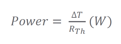
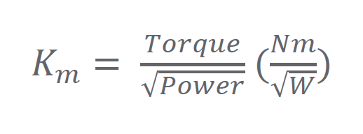
The motor constant is the ratio torque to the square root of power and can be utilized in addition to torque and speed to properly size a motor with thermal restrictions in mind. Using the calculated power dissipated and required torque, minimum required motor constant (𝐾𝑚) can be calculated.

Motor constantAlthough it seems this parameter remains constant with the motor, it in fact varies as the temperature of the system fluctuates, because of the changing resistance caused by winding heating. You can see this relationship in the equation below, where 𝐾𝑇 is the torque constant, and 𝑅 is the resistance.

Motor constant resistance

As the resistance increases due to Joule heating, the motor constant decreases. If you have a larger maximum allowable temperature, your motor constant will decrease.

Not all motor manufacturers provide information in the same manner. Some will list 𝐾𝑚 at ambient temperature, rather than a hot temperature, which means that the resistance would be at a minimum. Be aware of this inconsistency and look out for notes on datasheets that state temperatures at which the parameters are calculated.

In the example below, we have two system specifications: torque and speed. Imagine the operating temperature is known but is not communicated at the time of the motor selection process.

Motor Requirements
Torque≥ 0.4Nm of continuous torque
Speed≥ 900 RPM at maximum continuous torque


With these specifications in mind, we found a motor. In Figure 1 below, the motor meets the continuous Torque-Speed requirement of 0.4 Nm at 900 RPM.

UTH Motor Torque Speed ProfileFigure 1 – Celera Motion UTH-63-B-24-A-N-000 Motor Torque-Speed Profile at 24Vdc and 90°C temperature rise (130°C Max Temperature)

However, when the motor is installed into the housing and operated at the required torque and speed, the temperature exceeds what is allowed for this system at 130°C. If the torque-speed profile was run at the actual maximum operating temperature of 80°C (Figure 2 below), we would have seen the motor’s continuous torque specification fall short.

Motor constant software

Figure 2 – Celera Motion UTH-63-B-24-A-N-000 Motor Torque-Speed Profile at 24Vdc and 40°C temperature rise (80°C Max Temperature)


Now, the motor must be replaced, and we must start back at the beginning of the motor selection process.

In the next example, the maximum allowable operating temperature is known, and the required 𝐾𝑚 is calculated in addition to the original torque and speed requirements.

Motor Requirements
Torque≥ 0.4Nm of continuous torque
Speed≥ 1000 RPM at continuous torque
Calculated 𝐾𝑚≥ 0.09

If we use the same example shown above, and instead look at the 𝐾𝑚 values on the datasheets, we can verify that the motor in Figure 1 would not meet the system requirements, allowing us to find a new motor that satisfies both temperature limitations and the torque-speed point.


Table 1

Example of Motor Selection with system requirements and two different motors (one is shown at varying max allowable temperatures)

Motor selectionNote: system required 𝐾𝑚 is calculated.

The example above shows that neglecting the motor constant could be detrimental to the system in terms of safety, MTBF, and accuracy.  This also proves how much time could be saved by understanding the required motor constant.

Conclusion

Every mechanical system has thermal limitations, whether it be a safety requirement, MTBF, or thermal expansion concern. It is crucial that these heat sources are understood and considered when designing a system. By isolating your heat losses down to the component level, you can utilize a few simple equations to calculate the required motor constant for the system. Sizing a motor with the correct motor constant value allows your motor to achieve the torque required while maintaining alignment with the temperature limitations of your system.