While motor output power is an important consideration for all applications, motor efficiency is equally important for power-limited systems such as battery-operated applications. This paper will provide the equations needed to calculate input power, output power, motor power losses, and efficiency for properly sizing a motor, servo drive, and power supply for your application. It will also provide helpful examples of calculating motor power while clearing up common misconceptions about power supply and motor current.
Conservation of Power
It is important to understand that the power supplied to a motor is conserved, as electrical energy is converted to mechanical and thermal energy. That means that the difference in the power supplied to the motor and the power output from the motor is power lost through inefficiencies like heating and frequency-dependent hysteretic losses. A 100% efficient motor would be able to convert 100% of the input power to output power. However, all motors experience some degree of power loss. Let’s break down the dominant power components in motor operation.
Conservation of Power
All power to the motor is ultimately sourced from the bus power supply unit. If the goal is to choose a motor given an existing power budget, meaning the power supply voltage and current are predetermined, the available input power to the motor can be calculated as follows.

Eq.1
where:

Eq.2
Alternatively, if a specific application torque-speed point must be achieved and drive efficiency is known, we can work backwards to size the correct power supply unit using the equations below.

Eq.3
where:

Eq.4
If we assume a 100% efficient drive and therefore no power losses are present, supply power is equal to motor input power.
A common misconception is that motor current and power supply current are the same value. This can be true, but only when the motor is in the stalled condition and no output power is being produced. In this case, it also requires that the motor’s thermally limited stall current is equal to the bus voltage divided by the motor’s phase-to-phase resistance. In the stalled condition, equation 4 becomes:

Eq.5
Using equation 5 and substituting power supply current for motor current gives:

Eq.6
Isolate motor current in equation 6:

Eq.7
The power supply current and motor current are only equivalent when the motor’s thermally limited stall current is equal to the power supply voltage divided by the phase-to-phase resistance of the motor winding. As stated above, although we show that this situation is in fact possible, it is often not the case, as motors in most applications are not operating at the stall condition, nor is it common that equation 7 is true.
Motor Output Power
Output power of a motor is the resulting power that is available to move the load after all system losses have been accounted for.

Eq.8
Output power can be calculated by multiplying the application speed ![]() and torque (𝑁𝑚).
and torque (𝑁𝑚).

Eq.9
Motor Power Losses
There are two types of power losses in a motor – core losses and copper losses. While power losses in a torque motor are dominated by copper losses, it is important to understand what causes each source and how they affect the output power of a motor.

Eq.10
Core losses are caused by eddy currents in the stator’s iron core. While providing a rigid support for the copper windings and completing the magnetic circuit of the motor, the iron core also allows for eddy currents which create torque ripple in the motor. This is minimized by constructing the stator stack out of iron laminations that are bonded together. Eddy current losses are frequency-dependent and increase in high-speed applications. For certain motor designs where high speeds are targeted (>5 kRPM), frequency-dependent losses should be considered when calculating motor efficiency however, they are negligible to copper losses in our torque motors. Therefore, we will assume that motor power losses are equal to copper losses for the rest of this paper.

Eq.11
Copper losses are caused by heating, as current flows through the windings of a motor. Three-phase brushless motor theory tells us that power loss can be calculated using the equation below where the single-phase resistance is known.

Eq.12
Equation 12 assumes that the single-phase resistance can be measured. However, generally the neutral tap of wye-wound motors is not accessible – making it impossible to measure the single-phase resistance. Therefore, we must introduce phase-to-phase resistance into the equation above.

Eq.13
If current is not specified in units of 𝐴𝑅𝑀𝑆, use the equations below to convert current to units 𝐴𝑝𝑒𝑎𝑘 𝑜𝑓 𝑠𝑖𝑛𝑒 or 𝐴𝐷𝐶.

Eq.14

Eq.15
Now plug 𝐼𝐷𝐶 or 𝐼𝑝𝑒𝑎𝑘 𝑜𝑓 𝑠𝑖𝑛𝑒 into equation 13:

Eq.16

Eq.17
For more information on motor unit conversion, please read the technical paper linked here: Motor Unit Conversions – What They Mean and How They are Used – Applimotion Direct Drive Motors (celeramotion.com)
Overall power losses can also be calculated if the motor input and output powers are known.

Eq.18
Motor Efficiency
Motor efficiency is the ratio of the motor’s output power to input power. While 100% efficiency is ideal, in application, all motors will experience power losses that decrease the overall efficiency of the motor.

Eq.19
While motor efficiency is not commonly specified on motor datasheets, it is synonymous with the motor constant (𝐾𝑚). The motor constant reflects the motor’s ability to output torque given power losses.

Eq.20
Therefore, if you compare two motors of the same frame size and one has a higher 𝐾𝑚, that means for the same power loss, the motor with a higher 𝐾𝑚 has a higher torque output. Alternatively, a higher Km motor can output the same torque with lower power losses. For more information on the motor constant, please read our technical paper “Why Motor Constant Matters in Thermally Limited Applications”.
To determine what motor constant is needed for a specific torque requirement, first, calculate the dissipated power, then use equation 20 to calculate 𝐾𝑚.

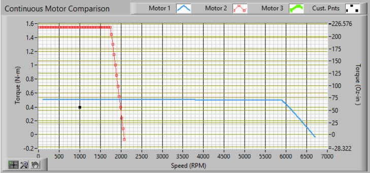
The application torque-speed point is 0.4 Nm at 1000 RPM (black dot in torque-speed plot above).
These torque-speed curves assume a 24𝑉𝐷𝐶 bus voltage with an ambient temperature of 25°C and allowable temperature rise of 130°C to a maximum winding temperature of 155°C. Additionally, these curves reflect the continuous torque output at the rated current. However, to better compare these motors, we need to reduce the current such that the torque output meets the application requirement of 0.4 Nm.
First, calculate the current needed to achieve 0.4 Nm of torque for each motor using the torque constant. This is a key motor parameter that is specified on most motor datasheets.

Eq.21
Isolating for current, this equation becomes:

Eq.22
Motor 1:
- Motor 1 𝐾𝑡𝑡𝑟𝑎𝑝(𝑙𝑜𝑎𝑑𝑒𝑑, ℎ𝑜𝑡) = 0.031 𝐴𝑁𝑚𝐷𝐶 (pulled from datasheet)


- Blue Curve: rated torque-speed curve (𝑇𝐶 = 0.5Nm) with rated current of 15.1 𝐴𝐷𝐶
- Red Curve: application torque-speed curve (𝑇𝐶 = 0.4Nm) with application current of 12.9 𝐴𝐷𝐶
Motor 2:
- Motor 2 𝐾𝑡𝑡𝑟𝑎𝑝(𝑙𝑜𝑎𝑑𝑒𝑑, ℎ𝑜𝑡) = 0.101 𝐴𝑁𝑚𝐷𝐶 (pulled from datasheet)


- Blue Curve: rated torque-speed curve (𝑇𝐶 = 1.55Nm) with rated current of 14.5 𝐴𝐷𝐶
- Red Curve: application torque speed curve (𝑇𝐶 = 0.4Nm) with application current of 4.0 𝐴𝐷𝐶
Now that application currents have been determined, calculate and compare the power losses of each motor using equation 16:
Motor 1:

Motor 2:

Due to the significantly reduced current, the power loss for Motor 1 is more than six times the power loss for Motor 2 when operating at the same torque-speed point.
While it is simple to calculate the power losses for a certain torque-speed point, the motor constant is a helpful indicator of motor efficiency. Let’s look at the motor constants for Motors 1 and 2 as specified in the datasheet. If we are correct in our assumption above, Motor 2 should have a larger motor constant than Motor 1.

As shown in the table above, our assumption is true – meaning that at the same application point, Motor 2 dissipates less power and is therefore more efficient than Motor 1.
More Motor Sizing Examples
Here are a few more examples of calculating motor power elements given drive, motor and application specifications.
1)
a.Calculate maximum motor input power given power supply voltage, current, and drive efficiency.
Known: Power supply can provide a maximum of 2𝐴𝐷𝐶 at 24𝑉𝐷𝐶. The drive we have selected has an efficiency rating of 97%.
Using equations 1 and 2:


b. Determine what 𝐾𝑚 is needed to achieve a torque-speed point of 0.5Nm at 1200RPM given the above available input power to the motor.
Before calculating the output power of the motor, convert speed from units of RPM to rad/sec.

Insert calculated speed and known torque into the equation 9:

Now that output power is known, calculate motor power losses using equation 18.

Now that output power is known, calculate motor power losses using equation 18.

2) Calculate heating losses of a motor given phase-to-phase resistance and motor current.
Known: The motor has a phase-to-phase resistance of 0.5 Ω with a continuous current draw of 7 𝐴𝐷𝐶.
Use equation 16 to calculate heating losses.

3)
a. Calculate required input power given application torque-speed point, motor-phase-tophase resistance, and motor current.
Known: The motor will be driven at 5200 RPM at a torque of 0.6 Nm. The phase-to-phase resistance is 0.1 Ω and the motor current is 17.3 𝐴𝑝𝑒𝑎𝑘 𝑜𝑓 𝑠𝑖𝑛𝑒.
Before calculating output power, convert speed from units of RPM to rad/sec using equation 23.

Insert speed and torque into equation 9.

Next, calculate the heating losses in the motor using equation 17.

Using equation 4, calculate the required input power to the motor from the drive.

b. Calculate the required power supply current for a 24 𝑉𝐷𝐶 supply given a drive efficiency rating of 98%.
Using equation 3:

Next, isolate power supply current in equation 2.

c. Calculate the efficiency of the motor at the application torque-speed point using equation 19.

Conclusion
Motor power equations are crucial for properly sizing a motor. This paper has provided several examples of how to determine parameters such as power supply voltage and current, input and output motor power, and motor efficiency, which is critical for battery applications such as exoskeletons and satellite communications. In these applications, sizing of power supplies, drives, and motors is best accomplished using the power equations described in this paper. It was shown how motor constant can be used as a measure of efficiency, as it reflects the motor’s ability to produce useful torque normalized by thermal power loss. Because of this, the motor constant 𝐾𝑚 is the single most important metric when choosing a motor for power limited systems.


