
The Challenge
Permanent magnet brushless motors come in all shapes and sizes providing both rotary and linear motion. They are known for high torque density and high efficiency. They are also routinely referred to as Brushless DC motors, Brushless AC motors, Synchronous Permanent Magnet motors, or Servo Motors. The fundamental output of these machines is torque (rotary) or force (linear).
Smooth and predictable torque/force while moving is the main challenge for many applications in imaging, scanning, metrology, photonics, and tracking. Traditional permanent magnet brushless motors exhibit cogging torque, a torque disturbance from the interaction between the permanent magnet and the slots between stator teeth. Cogging is cyclical torque with angle that creates torque ripple, (and corresponding velocity ripple), adding a non-linear element to the control of the motor.
Various methods to minimize cogging have been used for years, they include; skewing laminations, skewing magnets, special mechanical modifications, and electrical compensation in the motor controller. In most applications that require smooth motion with light loads the success of these methods is marginal.
The Solution
Slotless motors are designed to optimize smoothness and create predictable torque output with minimal non-linear effects. Commonly referred to as slotless motors when rotary and air core motors when linear, slotless motor designs place only copper phase coils in the air gap of the motor. These coils, when placed properly, interact with the permanent magnetic flux to create force or torque. Cogging torque is eliminated because the discontinuous iron teeth are removed from the motor air gap. Slotless technology is especially effective with direct drive precision systems because all torque is a function of phase current and there are no unwanted or uncontrolled torque disturbances from the motor
Motor Topology
There are two critical internal parts to a permanent magnet brushless motor. The permanent magnet assembly and the electromagnet assembly. In the rotary form these two parts are referred to as the rotor assembly and the stator assembly. In linear form, they are the magnet track and forcer. The rotor/magnet track is comprised of a magnetic steel component with permanent magnets affixed or buried internally. The stator/forcer is a multi-phase electromagnet with three phases as the most common construction.
The remainder of this technical note will focus on comparing and contrasting slotless and slotted rotary motors. The same principals also apply to air core linear motors and actuators.
Rotor and Stator Construction
Permanent Magnet Rotor Assembly
The rotor assembly typically takes the form of a steel ring or shaft with magnets attached. The magnets can be mechanically discrete or a single piece ring with the individual magnetic fields magnetized into it.
The number of poles is directly related to the number of permanent magnets on the rotor assembly.
Poles are sometimes defined as pole pairs, i.e. number of north-south pole pairs. The pole count is the transfer ratio between electrical frequency and mechanical speed. Typically, lower pole count motors run mechanically faster and higher pole count motors run slower, but modern high bandwidth electronics are increasingly capable of achieving high speeds from motors with high pole counts.
Figure 1a below shows an example of a rotor with mechanically discrete magnets from a Celera Motion Omni™ Series motor.

Electromagnetic Stator Assembly
In order for a motor to rotate, a number of electromagnetic phases are required. There are typically three phases in the brushless permanent magnet motor. These electromagnetic phases are energized through current outputs from a motor controller. The motor controller typically uses encoder feedback to monitor the position of the rotor and creates the correct current vector in the stator phase set to generate torque. Once torque is created, it can be controlled along with speed and position to handle any motion control application.
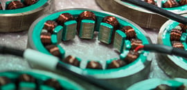
The stator assembly typically consists of soft iron laminations with radially protruding teeth. The spaces between these teeth are called slots and allow electromagnetic coil wire to be inserted. This motor type is termed slotted motor. Figure 1b below shows an example of a Celera Motion Omni™ Series motor.

Slotted Stator
Traditional slotted stator designs use teeth to focus electromagnetic flux towards the rotor magnets and reduce the overall air gap in the magnetic circuit. There are usually multiple teeth per phase. Slotted motors are the predominant motor topology because they provide a good balance between torque output, motor constant, efficiency, and manufacturability. Slotted motors typically yield the highest motor constant (torque/watt1/2) for a given motor size. They also provide high efficiency and high acceleration rates with lowest inertia.
As discussed above, the spaces between stator teeth allow for electromagnetic phase wire to be inserted. The slots are the primary cause of cogging torque because they create a discontinuous permeability as the magnets move past each slot. It is standard practice to skew or stagger stator teeth or rotor magnets to minimize the fundamental frequency of the cogging torque.
Figure 2 below shows a Celera Motion Omni™ Series stator with skewed teeth.

Slotless Stator
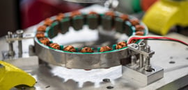
The perfect permanent magnet brushless motor has sinusoidal torque output with angle with no higher harmonic distortion. The slotless motor is the closest approximation to this goal. The slotless stator does not contain stator teeth or their corresponding slots. Phase coils are spatially oriented around the stator to form the electromagnetic phase relationship required for motor operation. When energized, the coils create an electromagnetic field similar to the slotted motor, but result in a torque versus angle curve that is sinusoidal. There is zero cogging torque because there are no teeth with corresponding slots.
Figure 3a below shows a Celera Motion Agility™ Series slotless motor with a rotor designed with mechanically discrete magnets.
Figure 3b below shows a Celera Motion Agility™ Series slotless motor with a rotor designed with a single piece ring magnet.


With a slotless motor, all torque is a function of current applied to the winding. This simplifies the servo control system and allows for smoother operation. The motor also has significantly better Kt linearity over its slotted counterpart.
One consideration with slotless designs is the large magnetic air gap between the rotor and stator due to the removal of stator teeth. This results in lower flux density and correspondingly lower torque output for a given size motor. The torque output of a slotless design is typically 70-75% of an equivalently sized slotted motor and Celera motion can optimize many Agility Series motor designs to achieve up to 85%. If smoothness is critical the slotless technology is preferred, but slotted motors are likely a better solution if continuous torque is the most critical requirement.
Torque Versus Angle Curve
The fundamental output of a rotary motor is torque, which is a function of both current and position. The most common method used to analyze this phenomenon is a torque versus angle curve. The torque versus angle curve depicts motor torque output, including cogging torque, and is the closest figure of merit to predict how the motor will perform in the application. Torque versus angle can be measured by energizing a motor phase while manually rotating the rotor and measuring the torque created with a torque transducer.
All brushless permanent magnet motors have a torque versus angle profile that is generally sinusoidal in shape. It usually contains several harmonics. Cogging torque is one of the contributors that can result in significant harmonic distortion. This distortion results in torque ripple as the motor is operating and will impact velocity ripple.
Figures 4 and 5 below illustrate how cogging torque is the key difference between slotted and slotless motor technologies. Figure 4 clearly shows that when a slotted this motor is not operating at its full rated torque, the cogging is a relative percentage of the output and torque ripple is significantly higher. It is easy to see in Figure 5 that there is zero cogging torque in the torque versus angle curve.


Summary & Conclusions
At Celera Motion, the product offering includes both slotted motors and slotless motors. Slotted motors are good for high torque density and high acceleration, while slotless motors are optimum for smooth operation and good Kt linearity when operating in a servo control system.
Cogging torque will vary greatly with different motor designs and steps are typically taken to minimize its impact, like skewing the magnet or stator laminations. Both technologies offer large through holes and can be designed for low profile direct drive applications. The key performance characteristics of each motor type are summarized in Table 1 below.
Table 1: Summary of key performance characteristics of slotted and slotless motors.
| Parameter | Slotted | Slotless |
| Smoothest Motion (Lowest Velocity Ripple) | ✔ | |
| Highest Torque Constant | ✔ | |
| Torque Constant (Kt) Linearity | ✔ | |
| Largest Through Hole | ✔ | |
| Highest Acceleration Rates | ✔ |
Slotless motor technology is offered in multiple product lines from Celera Motion, including Agility™ Series frameless rotary motors, Javelin™ Series frameless linear motors, Infinity™ Series arc-shaped frameless motors and AgilityRH™ Series rotary actuators.